Summary
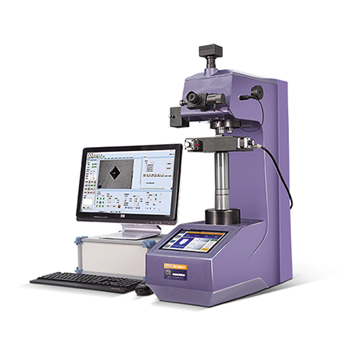
ZHVS-1 / 5 / 10 / 30 / 50AT EOS100B semi-automatic Vickers hardness measurement system, integrated optical imaging, mechanical displacement, electronic control, digital imaging, image analysis, computer processing and other current professional technology, through the computer host to control the micro Vicker hardness meter and automatic platform, and the hardness indentation digital imaging on the computer screen, and then through automatic reading, manual reading, accurate measurement of metal and part of non-metallic materials and various film layers, coating micro hardness, hardening layer depth, membrane layer thickness, two point spacing, etc. It can also photograph the metal surface morphology and print the fixed rate. This system breaks through the traditional hardness test method, realizes the automatic, high precision, high repetitive hardness test, and is an important equipment for material analysis.
Equipment Introduction
● Digital display automatic tower micro Vid hardness meter, through the LCD screen display results, and can display and set the test ruler, test force, pressure head type, retention time, conversion unit, etc.;
● Using 8-inch touch screen and high-speed ARM processor, intuitive display, man-machine interaction friendly, simple operation, large database storage, automatic data correction, and provide data line report;
● The fuselage uses cast iron primary casting molding, with the car paint treatment process, round and beautiful appearance;
● The worm worm lifting system can improve the test stability and accuracy of the test, without the need to focus again after the test;
● Equipped with automatic turret function, HD measurement and observation-double objective combination, combined with the built-in length encoder HD microscope, to achieve the imprint diagonal of one key measurement, better reduce the human operation interference and reading error;
● Convenient CNC system, can automatically conduct the full hardness ruler unit conversion;
● The maximum and minimum value of the hardness value can be set, and when the test value exceeds the set range, the beep will be emitted;
● With the software hardness value correction function, you can directly correct the hardness value within a certain range;
● With the database function, the test data is automatically grouped preservation, each group can save 10 data, can save more than 2000 data;
● With the hardness value curve display function, intuitive display of the change of the hardness value;
Choose choose software language
● CCD image processing system, and optional Nusi pressure head, for Nusi hardness measurement;
● Configure with wireless Bluetooth printer, and can output data through RS232 and USB interface;
● Precision is consistent with GB / T4340.2, ISO 6507-2, and ASTM E384.
| Vicket Ruler | 1 kg | HV0.01、HV0.025、HV0.05、HV0.1、HV0.2、HV0.3、 HV0.5、 HV1kgf |
| 5 Kg | HV0.3、HV0.5、HV1.0、HV2.0、HV3.0、HV5.0kgf |
| 10 Kg | HV0.3、HV0.5、HV1.0、HV3.0、HV5.0、HV10kgf |
| 30 Kg | HV0.3、HV0.5、HV1.0、HV5.0、HV10.0、HV30.0kgf |
| 50 Kg | HV1.0、HV5.0、HV10.0、HV20.0、HV30.0、HV50.0kgf |
| Test Force | 1 kg | 10、25、50、100、200、300、500、1000gf |
| 5 Kg | 0.3、0.5、1.0、2.0、3.0、5.0kgf |
| 10 Kg | 0.3、0.5、1.0、3.0、5.0、10kgf |
| 30 Kg | 0.3、0.5、1.0、5.0、10.0、30.0kgf |
| 50 Kg | 1.0、5.0、10.0、20.0、30.0、50.0kgf |
| Remarks | 1/5/10/30/50kgUsers can choose the appropriate configuration according to their own functional requirements |
Technical Parameter
●Test force selection: the test force selection is conducted by rotating the test force and changing the hand wheel, and the current test force is displayed on the screen
● Loading control: automatic (loading / retaining / unloading)
● Holding time 1-99 seconds (1 second as increment)
● Test mode: HV / HK
● Hardness value: hardness range 5-5000 HV, through the data measured on the micrometer, the data into the hardness meter to obtain the corresponding hardness value. Show a value error of 3-5% HV.
● Maximum height of specimen: 180mm, distance from indentation center to machine wall: 130mm
● Optical measuring system
| 1 kg | 1 kg | 1 kg | 1 kg | 1 kg |
| Objective | 10 (observation), 40 (measurement) | 10 (observation), 20 (measurement) |
| Total Magnification | 100 (observation), 400 (measurement) | 100 (observation), 200 (measurement) |
| Measuring Range | 200μm |
| Division Value | 0.025μm | 0.1μm |
●X-Y automatic object loading stage
Countertop size: 130X120 mm
Maximum stroke: 50X50 mm
Minimum step distance: less than 1 micron (0.001MM) (or 2 microns, optional)
Repeat location: less than 3 microns
Movement speed: adjustable;
Control mode: manual control, electric control, computer control;
● Light source: 12V / 20W
● Light source brightness: PWM dimming
● Energy saving mode: automatically enter the standby mode after 10 minutes
● Power supply: 220V, 50Hz
● Complete machine power consumption: 100W
● Total size: 500330560mm
● Weight: 36kg
Functional Profile
| 1. | The automatic recognition ability of diamond indentation image is far ahead of the existing mainstream hardness measurement software products. |
| 2. | Each functional area of the main interface can be dragged arbitrarily to form a personalized layout style. |
| 3. | Compatible with the measurement of the Nuss (HK) hardness, the Nuss indentation can be automatically identified. |
| 4. | In addition to the automatic measurement, there are also three manual measurements: four-point measurement, diagonal measurement and four-sided measurement. |
| 5. | Two calibration methods: hardness block calibration, optical calibration. |
| 6. | Standard hardness block calibration supports multiple calibration averaging. |
| 7. | The software automatically selects the best calibration coefficient for different resolutions, different objectives lenses and different loads. |
| 8. | During the hardness measurement, the best calibration coefficient is automatically selected according to the different hardness values. |
| 9. | When measuring manually, it has a magnifying glass function to easily find the indentation peak position. |
| 10. | Provide the head / lens offset calibration function, eliminate the mechanical deviation between the head and the lens, correct the overall system error, thus improving the accuracy of the hardness detection results. |
| 11. | Support a variety of video acquisition equipment, resolution: 1.3 million, 2 million, 3 million, 5 million digital cameras; display indentation video on the computer, can capture and store images. |
| 12. | When measuring the hardened layer path sequence, there are several flexible initialization modes to automatically save and import the previous path sequence; the measurement path can also be stored arbitrarily for reloading. |
| 13. | The measurement results are arranged according to the path sequence, and the corresponding depth value and hardness change curve of the hardening layer are generated. |
| 14. | Provide distance measurement and angle measurement function, and can display multiple groups of distances and angles on the video or image simultaneously. |
| 15. | Built-in standard hardness value conversion tools, referring to GB, DIN, ISO, ASTM and other standards, can be realized: Vickers HV, Nu HK; Roche: HRC, HRA, HRB, HRD, etc.; surface Roche: HR15N, HR30N, HR15T, etc.; Bush: HBS, HBW, any conversion unit can be selected to be included in the result table. |
| 16. | Report content and format can be flexibly set to automatically generate word and excel documents. All results, indentation images, custom information list, user Logo, can be set to the graphic report. |
| 17. | Password and administrative permission can be set: ordinary operators can only measure the hardness according to the set setting. |
| 18. | The software can automatically save the user's habitual Settings, keeping the last shutdown state at the next startup time. |
| 19. | Software provided: Chinese, English, German, Spanish, Russian (optional). |
| 20. | Automatic control function of hardness meter turret. |
| 21. | Pway planning function, 17 kinds of path planning free setting. |
| 22. | Area mode & continuous test function. For multiple indentation in the same field of vision, the area mode can be selected, and only the indentation in the scope of the set range can be considered for each measurement. The area mode opened during continuous testing can avoid the interruption of the test caused by multiple indentation in the same field of vision. |
| 23. | Surface correction function, conform to Table 1 and Table 2 of ASTME384 standard, and provide the test correction requirements of curved parts such as ball and rod. |
| 24. | NS automatic identification and measurement, can input head angle correction, ASTM E384-11, Sec. 10.7. 2.1. |
| 25. | Vickers and Nous measurements introduced the effectiveness alarm function for suspicious shape indentation that do not meet the ASTM E384 standard. |
| 26. | The multi-sample panoramic scan function can conduct a panoramic scan of multiple samples, and then plan the path on the panorama, and finally complete the continuous test. |
| 27. | Scanning area free setting function. For irregular samples, the scanning area can be set according to the shape to narrow the scanning area and improve work efficiency. |
| 28. | The CHD hardening layer test function can set the stop condition according to the need, and interrupt the test process in advance when the test conditions are met. The original purpose of this function is to save time after the CHD test reaches the hardening layer limit. |
| 29. | The ror and repetition assessment were used to ensure the calibration. |
| 30. | Automatic brightness function, can automatically adjust the surface of the sample to the best state, the appropriate brightness can better distinguish the indentation from the surrounding, help identify the indentation peak more precisely. |
| 31. | The minimum interval generates test points to obtain a more detailed and accurate sample hardness distribution. |
| 32. | Built-in pre-sense tooth template can greatly save the setting time of complex and time-consuming test points, especially like the setting of dentate flanking measurement points. All standard presets such as HK30 and HK0.5 can be implemented in one device. The corresponding reports are also stored. |
| 33. | Fracture toughness. The system allows the user to continue to measure the crack size (through the most extreme of the left and right sides of the crack) to calculate the fracture toughness. The system shows 3 more columns in the hardness measurement result table: C1, C2 and Kic. C1 is the distance from the most left end to the most right end of the crack (unit mm), C2 is the top to the bottom distance, the total crack length L = C1 + C2-D1-D2 (D1 and D2 are the measured indentation diagonal length), fracture toughness is calculated according to Kic = 0.0028 * sqrt (Hv * F / L), Hv is the measured hardness indentation, F is test force unit N, L unit m, Kic unit MPam ^ 1 / 2. Different calculation methods are provided later. Like the indentation, the crack size will be marked by a rectangle, the user can drag the rectangle to modify, and automatically update the calculation result statistics. In the statistics column, the fracture toughness selection is displayed. If checked, the statistical result is the fracture toughness Kic, and if not selected, Hv. Reporting (WORD and EXCEL) automatically adds the C1, C2, and Kic columns. Note: When using the fracture toughness, the above Nusi hardness should be unselected. |


Path Planning Function
As an extension of the measurement function, in the "measurement path" page, it provides 8 ways to complete the precise planning of the path to be measured.
| Path Planning | basic function |
| Free Selection | Select any position of the image to become the path to be measured. |
| Any Direction | Point selection meaning starting point, a straight line segment in any direction. |
| Edge Normal | The normal segment is automatically generated near the dot selection edge. |
| Two-point Normal | Select the edge two ends to generate the central normal segment. |
| Angular Bisector | The three-point Angle is constructed to generate the angular bisector segment. |
| Arc Path | Two points to determine the center / radius, along the time to generate the path. |
| Edge Contour | Select near the edge and automatically generate the path along the edge. |
| Edge Isometric | Along the edge, select the point distance to generate isometric line segments. |
| Sawtooth Waveform | The period, tooth height and tooth symmetry can be quantified. |
| Two Points Center | Point selection means two points, determine two points center |
| Path Planning | Advanced Features |
| Line | Point selection meaning starting point, the line segment of any direction, the middle variable distance |
| More Lines | Multi-line path point |
| Sawtooth | The serrated multiline |
| Interpolation | A fixed number / distance path point is inserted between two points |
| Matrix | The path point of the rectangular array |
| Wheel | Wheel path point |
| Loop | Ring path point |


Panoramic Scan
Select the "Set Scan Range" function under "Panoramic Scan", and select how to set the scan range (specify coordinates, rectangular vertices, multilateral vertices) and motion mode (accuracy first, speed first) on the "Set Panoramic Scan Range" interface as shown in the following figure. Scan range vertex setting When selecting rectangular vertices and multilateral vertices, please first go to the current video window to select the vertices by following the prompts, and then click the "OK" button to set the scan range. If the range is not set in the current video window, the "Set Panoramic Scan Range" window is closed, and the user should set the scan range first.

The software interface right-click menu provides the functions to move to the point, display the path, delete the selected path point, import the current image, save the image, and so on.

For the one-yuan coin on the XY automatic platform, set the scanning range of 2015mm for panoramic scanning. The HDS system controls the motor to move and captures the resolution of 640*512, and finally connects more than 2500 pictures into the effect picture shown in the following page.

Free Set the Scan Area
The scanning area function is set freely. For irregular samples, the scanning area can be set according to the test shape of the sample to narrow the scanning range, so as to save the scanning time and improve the work efficiency.

Multi-sample Panoramic Scan


Path Planning Operation On The Panoramic Image: click "Import to the current image" to import the image content displayed in the current panorama interface into the "Current Image", and conduct path planning operation in the "Current image" according to the operation instructions of the path planning function.